SOLID STATE FLASHER BASICS
This lesson will help you understand the Triac or "solid state AC switch", a
basic circuit that is used in all solid state flashers to turn on and off the lamps
or neon transformers inside a sign.
The simplest form of flashing circuit can be seen in the diagram below. If you were asked to
build such a circuit you would be able to select the proper size wire, the proper lamp socket,
A source for the AC power, and a switch with the proper current and voltage rating.
The only thing different between this circuit and that of a solid state flasher is instead of a switch
to turn the lamp on and off a solid state switch called a Triac is used. A triac has a voltage and
current rating just like a switch.
There are no levers or buttons on a triac to turn it on and off...
instead a voltage is applied to a third lead on the triac to turn it on and off. This lead is called the Gate.
In effect the gate of the triac "opens" and "closes" the triac allowing current to pass through it.
Below is a picture out of the TECCOR Triac catalog. After 16 years of using this brand of triacs I highly recommend
them as original parts on new designs and as replacement parts for repairs. The picture shows the different case
styles you may encounter in the field. Note that all of the devices have three leads. The two high power
leads that the AC current flows through are called Main Terminal One (MT1) and Main Terminal Two (MT2).
The third lead is the Gate (G).
A basic triac circuit looks like the picture below....
when a voltage is applied to the gate of the triac the MT1 / MT2 terminals allow AC current to pass through
them. Removing the voltage shuts off the triac.
How the voltage is applied to the triacs gate is the next thing we will discuss. Some companies will drive the
triacs gate directly from an electronic circuit that determines when the triac is to be turned on and off. This kind of
drive solution is useful in high speed video displays. The kind with the R/G/B/W lamps in a cluster to form a pixel
of a full color reader board. While an increase in speed may be the advantage to this kind of
circuit the disadvantage is that if the triac happens to short internally from MT1 or MT2 to the Gate
a high voltage AC current is passed back through the triac and usually destroys the related drive
electronics also. This is a trade off that some engineers are willing to live with in order to gain the
speed necessary to keep up with the changing video to be displayed.
Standard solid state flashers can operate effectively without this increase in speed. More protection is included
in these kinds of designs. One common method is to use a chip called a Opto Triac Driver. The advantage
of this kind of design is that there is no physical connection between the sensitive drive electronics and the triac
turning on the AC loads. A beam of light, from a Light Emitting Diode (LED), shines across a narrow
space inside the chip onto a small, low current, triac also located inside the chip. This tiny
triac has a gate that is sensitive to light, not voltage, it is wired to the gate on the big
load bearing triac and turns it on and off.
The Opto Triac gets its voltage from a resistor that is tied to one side of the big triac.
At its simplest this is the basic circuit used in all Solid State flashers. Before I get some hate mail from some
overly sensitive engineer let me also point out the following details that were left out.
1. VAC hot and VAC neu can be reversed without affecting the operation of the triac.
2. MT1 is usually connected to VAC neu while the load is connected to MT2. The other side of the load goes to VAC hot.
Check your local codes, some say VAC hot must be switched others say VAC neu.
3. There is normally a fuse connected between the load and the triac.
4. A resistor and capacitor, in series, are usually connected across MT1 and MT2 as a "snubber"
circuit to prevent AC current from leading AC voltage into the triac when driving an inductive load
like a neon transformer - to prevent the triac from getting damaged.
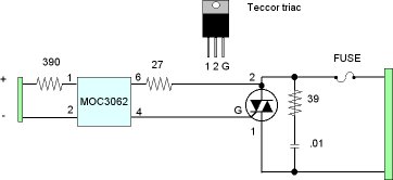
Here is the schematic diagram of a common solid state flashers triac circuit. All of the circuit details have
been put in so you can see the final circuit.
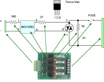
Now lets look at a common solid state flashers Triac board and see if you have learned enough to identify the major components, making your wiring job easier.
Looking at the location of the small opto isolated triac you can see the green connector that must be the voltage input from
the controller board (not shown) that contains the flasher sequences.
Finding the triac is no problem now. It is the device bolted to the heatsink.
The fuse indicates that you are near the output connector that goes to the AC load. One connection goes to
the load whose other side connects to VAC hot. The other connection (and it could be one common connection) connects to VAC neu.
By knowing the basic operation of a solid state flasher you are able to grasp the proper wiring procedure for
any brand of flasher.
To exit from this page you must click on your "Back" button.